
Belt Drive Power Transmission: Effective Pull, Speed and Belt Selection
A buyer may request an industrial transmission belt for a motor described only as “2 kW.” That number is useful, but it cannot identify a safe replacement. Two drives with the same motor power may use different pulley diameters, speeds, wrap angles and loading cycles, so their belt and shaft requirements differ.
Belt drive power transmission depends on the force available at the pulley and the speed at which that force acts. In a simplified steady-state model, transmitted mechanical power equals effective tangential belt force multiplied by belt speed. For friction drives, that effective force is related to the difference between tight-side and slack-side tension. This engineering relationship helps frame a specification, but it is not a standalone belt-capacity calculation or permission to increase installation tension.
How Does a Belt Drive Transmit Power?
A drive pulley applies torque to a belt, which carries motion to a driven pulley. In a friction-based V-belt or flat-belt drive, pulley contact and sufficient span tension enable force transfer. In a synchronous timing-belt drive, the belt teeth engage matching pulley grooves. The mechanisms differ, even though both transmit power through a flexible belt and create loads on shafts and bearings.

The engineering article Power transmission of a belt drive explains circumferential force, tight and slack spans, torque and the role of pre-tension for friction drives. Use these relationships as a framework. Do not transfer a general friction coefficient or a simplified V-belt tension assumption to a toothed-belt system.
Before evaluating a replacement, establish whether the original assembly is a wrapped V-belt, raw-edge cogged V-belt, nylon-sandwich flat transmission belt or synchronous tooth belt. The same stated motor power does not make these products interchangeable, because they require different contact geometry, pulley profiles and installation procedures.
The Three Calculations Buyers Should Understand
1. Power is force multiplied by belt speed
Under an ideal steady-state mechanical model:
P = Fₑ × v
Where P is mechanical power at the considered drive stage in watts, Fₑ is effective tangential force in newtons, and v is belt speed in metres per second. The formula describes the force associated with transmitted power at that speed. It does not give the tensile force in each span or the belt’s rated working tension. Use actual mechanical power at the assessed drive stage, not electrical input power or the assumption that motor nameplate kW is continuously transmitted under every load.
If a manufacturer supplies torque instead of power, M = Fₑ × r relates torque M in newton-metres to effective tangential force and pitch/effective radius r in metres for the appropriate contact geometry. Do not use an arbitrary outside diameter when the drive manufacturer specifies a particular pitch or effective diameter.
2. Tight-side minus slack-side force
In a simplified two-pulley friction-drive model, Fₑ = T₁ − T₂, where T₁ is the tight-side tension and T₂ the slack-side tension under the defined operating condition. Crucially, neither is generally zero. Both contribute to the forces experienced by the shaft and bearings.
These relationships do not determine the installation pretension from the power alone. Wrap, pulley surface condition, geometry, friction characteristics, duty cycle and the selected belt drive influence the necessary tension and available traction. The site’s working limits and supplier’s installation specification take precedence over a back-of-the-envelope calculation.
3. Belt speed links the force to power
For an ideal pulley contact without slip, v = πDn/60, with effective pulley diameter D in metres and speed n in rpm. A different pulley ratio changes the belt speed and torque distribution. For an actual drive, confirm the transmission ratio and any relevant slip or control effects. The LKBELT conveyor drive-layout guide covers geometric concepts for conveying belts; a power-transmission belt requires its own drive-specific geometry.
Keep three force concepts distinct: effective tangential pull (T₁ − T₂ in the simplified friction model), actual tension in each span, and the vector resultant applied to the pulley shaft/bearings. They are not interchangeable design values.
These are physics relationships, not a belt selection standard. Actual drive design must account for peak torque, startup, service factors, shaft and bearing loading, pulley profile, belt construction and the equipment manufacturer’s allowable limits.
Worked Example: Why Power Alone Is Not a Belt Rating
Imagine a hypothetical drive stage transmitting 900 W at an ideal belt speed of 1.5 m/s. The model yields:
Fₑ = 900 ÷ 1.5 = 600 N.
At the same hypothetical 900 W but 3.0 m/s belt speed, the effective force would instead be 300 N. This shows why identical mechanical power can imply different forces; it does not establish a safer belt or a permissible design margin.
If the effective pulley radius at the original 1.5 m/s stage is 0.05 m, the corresponding ideal torque is 600 × 0.05 = 30 N·m. These figures are mathematical illustrations, not tested LKBELT product specifications and not recommended design margins.
What remains unknown? We have not calculated T₁ or T₂ separately, installation tension, bearing radial load, belt working stress or pulley wrap. We also lack service factors, transient loads, pulley profile and the selected belt’s allowable capacity. Thus, a 600 N effective pull does not prove that any 20 mm-wide belt will work. Belt rating requires the original machine and manufacturer’s design method.
A useful procurement outcome is to ask engineering for the missing facts instead of using “900 W” to pick a belt solely from its appearance or width.
Why Tightening the Belt Does Not Solve Every Power Problem
For a friction drive, insufficient traction can cause slip and heat, but simply increasing pretension may overload bearings or accelerate belt damage. The effect of a tension change depends on pulley contact and drive geometry. The Gates industrial belt tension guidance makes clear that tension values depend on the selected V-belt or synchronous-belt drive configuration; its calculated outputs apply to the specified Gates components and cannot be copied as LKBELT ratings.
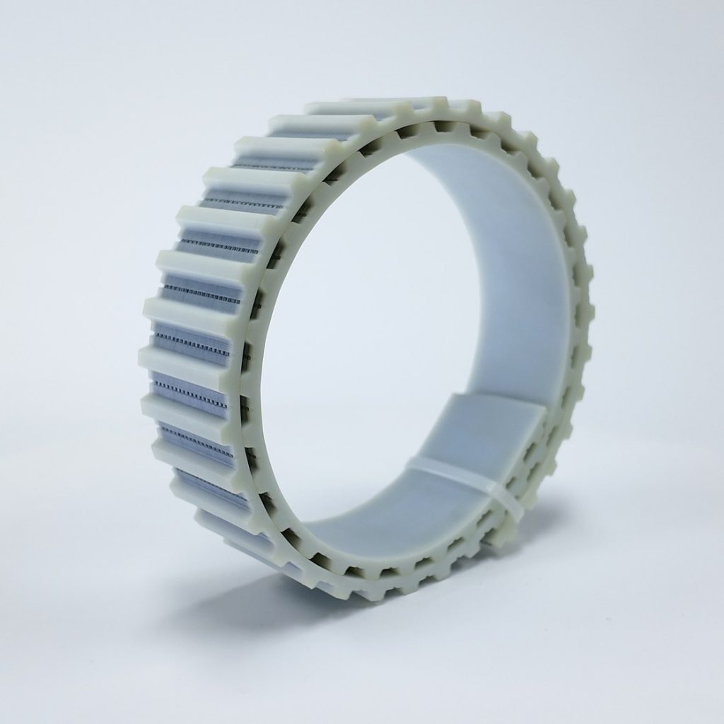
An apparently weak drive may instead have worn pulley grooves, incorrect belt section, contamination, improper alignment, a ratio error or unusual driven load. If a new belt slips, those machine issues require inspection before purchasing a stronger or narrower variant. The LKBELT V-belt size chart is useful for identification, not for approving an arbitrary transmitted-power rating.
For synchronous belts, the primary engagement is positive rather than friction-based. The correct pitch, tooth family, width, pulley teeth and recommended installation tension are especially important. A timing belt with a similar length but different tooth profile can create tooth interference and premature wear. The industrial timing-belt guide supplies product-family background, while the actual pulley-and-belt approval remains drive specific.
What Changes the Allowable Power of a Belt Drive?
Operating speed and pulley geometry
A changed pulley diameter alters belt speed at a given shaft rpm and influences bending and wrap. A very small pulley may limit a thick or heavily reinforced belt even when power demand seems moderate. Conversely, a larger pulley can change shaft packaging and bearing loads. Supplier charts and the equipment OEM define the permitted choices; do not infer capacity from diameter alone.
Peak torque and start-stop duty
Motor nameplate power is not the same as the most demanding operating event. Startup, acceleration, braking, reversing, intermittent loads and jams can produce conditions beyond a nominal steady-state value. Request the load profile or design-duty information from the equipment team. A simple P = Fv example does not capture transient dynamics.
Belt construction and joint
An industrial flat transmission belt may have a layered carcass, surface coatings and a specified end joint. A rubber V-belt may be wrapped or raw-edge, and timing belts have tooth and reinforcement choices. Each design responds differently to bending and tension. The joint, where applicable, can require separate approval for the smallest pulley and running stress.
LKBELT’s RNR15 nylon sandwich flat transmission belt identifies a specific layered belt with green and yellow faces and a published minimum-pulley reference. That is model information; it does not establish an allowable power rating for a buyer’s machine. Compare the actual width, loop length, splice and drive duty to the original specification.
The published T10 polyurethane timing belt is a separate synchronous-belt example. Its tooth family must be matched to the mating pulley; it must not be substituted into a friction V-belt drive because of a similar motor-power figure.
Shaft, bearing and mounting capacity
Power transmission is also a load on the machine. The tight- and slack-side forces produce a resultant pulley load that acts on the shaft and bearings. The force direction depends on the span geometry. The machine designer must check shaft, bearing, coupling and mount limits, particularly if pulley size, belt count, belt section or pretension changes.
The distinction between effective pull and the total shaft load is crucial: T₁ − T₂ describes the net tangential force in the simplified model; it is not automatically equal to the radial load on the shaft. The latter involves the vector combination of span forces and their angles. This is one reason replacing a V-belt drive with a different construction can require engineering approval even when motor power remains the same.
Procurement Check: Data That Are Often Missing
| Available statement | Why it is insufficient | Better information to obtain |
|---|---|---|
| “Motor is 2 kW” | Says little about pulley force or actual duty | Output torque, speed range, load cycle, reducer details |
| “Belt speed is 2 m/s” | Does not define traction, belt profile or working loads | Power at drive stage, pulley data, operating conditions |
| “Pulley diameter is 80 mm” | Contact/pitch diameter may be different | Drawing, profile, tooth count, measurement reference |
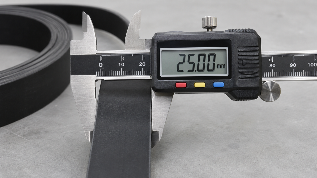
| “Belt is 25 mm wide” | Width alone is not a power-capacity approval | Exact belt model, construction and manufacturer rating |
| “Tension feels normal” | Subjective and unsuitable for approval | OEM/supplier tension specification and method |
| “The replacement is the same length” | Does not establish tooth, groove or joint fit | Cross-section/profile, length convention, pulley compatibility |
| “It ran in a brief test” | Short observation may miss peak loads | Defined load trial and equipment authorization |
This checklist is deliberately different from a generic list of all belt types. It directs a buyer from incomplete requests toward the mechanical data that affect a specific transmission belt purchase.
Two Industrial Selection Scenarios
Scenario A: same motor power, different pulley speed
Two hypothetical machines use motors with identical rated power. One has a different reduction ratio and pulley diameter from the other, so the belt speed and torque requirements at the drive stage are not identical. An old belt marking on one machine therefore does not approve that construction for the second machine.
Engineering should obtain the actual drive speed and torque, pulley dimensions and profile, expected load cycle and belt working limits for each position. Procurement may request candidates from the same belt family, but an identical material name or width is not a substitution specification. A shared belt model is acceptable only if the supplier and machine requirements support both duties.
Scenario B: repeated slip after a flat-belt replacement
A flat transmission belt is replaced with a visually similar belt, but the new drive slips under heavy load. Rather than increasing tension until the symptom stops, qualified maintenance documents pulley condition, actual belt-to-pulley contact, tension against the OEM value, alignment and load. A worn pulley or altered surface could make a compliant belt behave differently.
If a new belt construction is proposed, verify its contact surfaces, pulley diameter, joint and permitted working limits. The approval test needs to address the real loaded operating phase, not just no-load rotation. Neither the calculation example nor a catalogue photograph proves suitability.
Industrial Belt RFQ: The Decision-Ready Minimum
Supply the equipment model and drive position, original belt reference, belt family, pulley drawing, shaft speeds, ratio, transmitted power or torque at the applicable stage, normal and peak duty, ambient conditions and any reversing. For friction drives, include pulley contact conditions, wrap and OEM tension requirements; for synchronous belts, include tooth pitch/profile, pulley tooth count and approved tension method.
Add finished belt width and length with their conventions, total construction, reinforcement where documented, surface coatings, joint information and observed failure evidence. Ask the belt supplier to identify the proposed model, required deviations and missing approval data. Obtain equipment engineering acceptance before implementing a redesign or changing motor-side geometry.
A first-article check should validate the supplied construction and finished dimensions, then follow the machine’s safe installation and operating procedure under a representative duty. Record any agreed substitution and its drawing revision so repeat orders do not rely on informal descriptions such as “the green belt from last time.”
Frequently Asked Questions
What is the formula for power transmitted by a belt?
In a simplified mechanical relationship, P = Fₑv, where P is watts, Fₑ is effective tangential force in newtons and v is belt speed in metres per second. It is not a complete belt-rating formula.
Is effective pull the same as belt tension?
No. For the ideal friction-drive model, effective pull equals the difference between tight- and slack-side tensions. Neither individual span tension is defined by the difference alone.
Can I select a replacement belt from motor horsepower?
Not reliably. Obtain drive-stage speed or torque, pulley geometry, belt profile and complete operating-duty information, then use manufacturer-approved selection data.
Do timing belts use the same friction-drive equations?
Basic power and torque relationships still apply, but tooth engagement, permissible tension and load-sharing requirements must use the appropriate synchronous-belt design method, not a V-belt friction assumption.
Does more belt tension always increase safe power capacity?
No. Excessive tension can overload bearings and the belt and does not cure incorrect geometry or pulley condition. Follow the specific equipment and belt manufacturer’s instructions.
Send a Transmission-Belt Specification for Review
Once the belt family is identified, provide the original belt/pulley references, drive-stage mechanical speed and power or torque, start-stop duty, finish dimensions, belt surface, joint (if applicable), tension specification and quantity. For synchronous drives, add the matched tooth profile and pulley data. Send LKBELT the belt inquiry for model-level review; the machine designer must authorize changes to the drive or shaft loads.
Conclusion
The useful calculation in belt drive power transmission is a starting point: it links power, effective pull and speed and reveals why a motor rating alone is insufficient. A reliable industrial replacement also requires the actual belt family, pulley geometry, tension and load profile, plus confirmation of the shaft and bearing limits. Give LKBELT the original belt reference and complete drive data for a model-level review; treat any change of belt type or drive arrangement as an engineering decision, not a catalogue shortcut.