
A replacement timing belt can mesh with every pulley and still bring each cleat to the transfer point too early. A drawing that ties the cleats to the teeth gives the supplier a way to reproduce that timing.
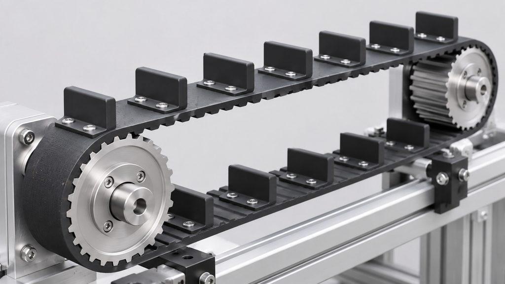
Specify custom timing belts as finished assemblies. Confirm the base belt and mating pulleys, then define the cleats, backing, holes and joining requirements on the same drawing. Give the supplier the tooth reference, direction of travel and machine clearances, and agree on how the finished belt will be checked before placing the order.
An OEM part number helps identify the original assembly. When a supplier needs to reproduce it, the drawing and the machine layout show which features determine fit and timing. Use an existing belt to fill in missing details, with wear and any differences from the drawing marked for review.
What Makes a Timing Belt Custom?
The base belt meshes with the pulleys and carries the working tension through its tensile members. A custom feature changes how that belt contacts the product, carries a fixture or fits a particular station. It might be an outer backing, a row of cleats or a pattern of holes. Each feature should have a purpose the supplier can see in the drawing or application notes.
A custom polyurethane timing belt can have several such features on the same assembly. Define where each applies. A belt with a backing over its full length presents a different surface to a return roller than one with pads at intervals. The drawing should show what passes through each contact point, including any joint or transition.
Start With the Base Belt and Mating Pulleys
Record the belt designation and check the pulley drawing for the mating tooth system. Tooth pitch is the distance between corresponding points on successive teeth. Matching pitch establishes that interval. Matching tooth shape and pulley groove geometry establishes whether the teeth are intended to engage. Include the pulley tooth count or drawing reference, usable face width and any flanges or guiding features that constrain the assembly.
For an endless belt, give the tooth count or specified pitch length and say how any other length was measured. An outside circumference taken over a backing describes a different path from pitch length. State the finished width and identify where overall width must include attachments or projecting hardware. Record the tensile-member construction if known, the supply form and the full pulley route, including any back-side idlers. BRECOflex Timing Belts 101
LKBELT lists SFAT10-PAZ PU timing belt and RPP5M-PAZ PU timing belt as distinct designations. Use the complete marking to start the inquiry. The RPP5M-PAZ page asks for a pulley drawing or belt reference, finished dimensions and any required backing or tooth facing. Specify which side carries the surface treatment. A general profile table can help identify the tooth family, while the approved drawing defines the supplied assembly.
Which Custom Timing Belt Features Can Be Specified?
An outer backing changes the surface that contacts the product or machine. Define the contact duty and the required surface, such as grip during indexing, release at discharge or cushioning against a sensitive face. A tooth-side facing serves a separate interface and should be called out separately.
Cleats and attached profiles project from the belt to locate, separate, guide or carry items. Show which face does the work and how force acts on it. BRECOflex describes welded and mechanically attached profiles in its own range, along with machining and perforation options. For each proposed feature, ask the supplier which methods are approved for the exact base belt and the proposed combination. BRECOflex custom timing belt options
Holes, grooves and cutouts need dimensions and a stated purpose. A locating hole for hardware and a clearance slot in a backing may require different depths and preparation. Show what each feature passes through and where it lies relative to the teeth, belt edges and any other attachments.
How Should Cleats Be Positioned and Dimensioned?
Give each cleat a side and plan view. Show its height from a defined mounting surface, width across the belt, thickness along the belt and working face shape. Mark the running direction, the face that leads and the lateral position from a named edge or centreline. Show hole size and position, how fasteners sit in the finished assembly, and how much room the hardware and cleat need as they travel around a pulley.
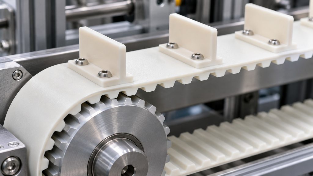
Tooth pitch and cleat spacing describe different dimensions. State the centre-to-centre spacing or list each cleat position if the intervals vary. Identify the first cleat relative to a defined tooth or machine reference, then show how that reference transfers to the belt drawing. Specify whether you are locating the cleat centre, mounting hole or working face. If the machine uses two belts together, show the required alignment of corresponding cleats.
On a closed loop, include the interval from the last cleat back to the first. Where there is a joint, locate it on the same layout so the supplier can check proximity to the attachments. A useful drawing makes it possible to verify both the cleat pattern along the belt and the timing of that pattern relative to tooth engagement.
LKBELT’s cleated PU timing belt for tobacco machinery shows projecting cleats and visible fasteners. Its drawing checklist asks for the cleat shape, spacing, alignment with the teeth and attachment details. A close-up helps identify the construction. The drawing or labelled sample is needed to establish dimensions and positions, as the tobacco processing machinery belt guide explains.
How Do Backings Affect Belt Fit and Operation?
Describe what touches the outer surface and when. A packaging line may require the belt to carry a carton through acceleration and then release it at discharge. An accumulation station can involve relative movement between the belt and the product. Give the supplier the contact material, load, cycle, temperature and cleaning exposure so the proposed surface can be evaluated for that duty.
Specify finished thickness on a defined measurement basis and show where the backing stops, starts or changes height. Check guide gaps, return rollers and clearance during installation as well as in the running position. A thicker backing can reduce clearance and change how the assembly bends. Grip and wear also depend on the contact pair and how it operates.
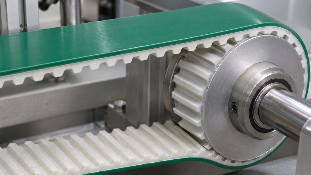
The BRECO and BRECOFLEX processing guide gives coating-specific bending guidance and discusses counter-bending and interrupted coatings for its own belt constructions. Ask for the permitted bends for the finished build, including any grooves, pads or local changes in thickness. The unmodified belt’s bend limit alone leaves those features unaccounted for. BRECO and BRECOFLEX belt processing guide
How Do Joints, Holes and Reinforcement Affect Compatibility?
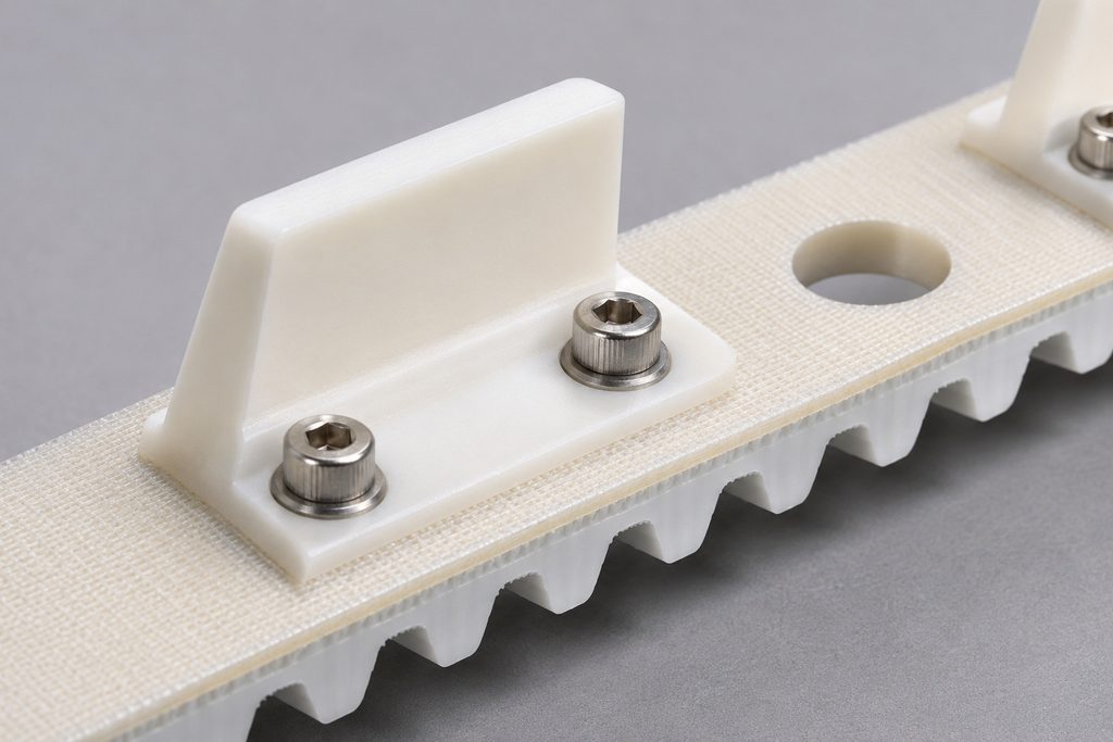
Tensile members carry belt pull. Before approving a hole or cutout, have the supplier review its location and depth against the actual cord layout. An attachment also needs a supported fixing arrangement and enough clearance through the pulley and guide route. A visible fastener on a reference sample provides a useful photo detail. The fixing drawing establishes how the hardware is retained and which parts of the belt it affects.
Specify whether the machine takes open-ended stock, a factory-made endless belt or a belt joined into a loop. A factory-supplied loop can have different reinforcement continuity depending on how it is made, so confirm the offered construction. If access requires joining after the belt is routed through the frame, confirm that the supplier approves that joining arrangement for the modified belt. Ask where the joint can sit relative to cleats, holes and backing transitions, and how the finished section will pass through the tightest bend.
Custom Timing Belt Specification Matrix
| Design feature | Buyer-provided specification | Machine compatibility | Supplier confirmation |
|---|---|---|---|
| Base belt | Full designation, profile, pitch, tooth count or pitch length, finished width | Pulley engagement, usable pulley face and guide fit | Mating tooth system and tensile-member construction |
| Cleats | Working face, dimensions, count, spacing, first-cleat reference and running direction | Indexing position, wrap clearance and transfer timing | Attachment drawing and positions referenced to the teeth |
| Backing or facing | Side, material or contact requirement, surface finish and thickness basis | Contact, guide gap, return rollers and repeated bends | Finished build and approved bend conditions |
| Holes or machining | Feature size, depth and location from tooth and edge references | Cord integrity, fastener clearance and guide contact | Approved feature location and processing for the offered construction |
| Joint and supply form | Required loop or open form, joint location where applicable and fitting access | Installation route, local profile and return path | Approved construction and permitted field joining, if needed |
Two Practical Industrial Scenarios
Tobacco machinery replacement
Suppose a maintenance team has a worn cleated PU timing belt and an OEM part number. A sample appears to match the pulley, but the cleat must arrive at a locating station in phase with the machine. Check the original tooth system and finished size, then establish where the cleat’s working face falls relative to the reference tooth and where its fastener sits. Record the clearance around the return. If the worn sample and the OEM drawing disagree, ask which dimension governs before approving a remake.
Packaging indexing system
Suppose a packaging machine needs a backing to hold cartons through a stop-and-start movement. Two suppliers offer the same nominal backing material. One proposal covers the full belt and the other uses pads at the carton positions. Compare contact area at the indexing station, finished thickness at the guide, and bending at the return idler. Ask each supplier to show those features on its finished assembly drawing and agree how the approved sample will be checked under the machine’s specified conditions.
What Should Buyers Submit With an OEM Timing Belt RFQ?
Start with the machine model, belt position, OEM part number and original belt marking. Attach the current drawing revision, pulley details and labelled photos of the tooth side, outer face, edges, attachments and joint. Mark any sample dimensions that come from a worn belt or any details that still need approval.
Include the finished width, length basis or tooth count, backing and facing requirements, cleat and hole layout, and the required supply form. Give the running direction, pulley and idler route, installation access, speed, load, indexing cycle and relevant operating or cleaning exposure. State the quantity, whether a first article is required and which drawing revision the quotation should reference.
Ask each supplier to list deviations against the same drawing. Confirm who will issue and approve the finished assembly drawing and which features require measurements or a sample check. Agree the inspection method and tolerances where fit or timing depends on them. For example, specify how to check the working face of the first cleat against the reference tooth and how to measure overall thickness at a backed section or joint.
On receipt, check the belt identity, tooth count or specified length, finished width, cleat positions and orientation, hole locations, joint and relevant finished clearances against the approved drawing. Agree separately on any machine fit or indexing check under the OEM’s procedure. A dimensional inspection and an operating acceptance check answer different questions.
Frequently Asked Questions
Can two timing belts with the same pitch use the same pulley?
Confirm the exact tooth profile and mating pulley geometry. Also check usable width and guidance before approving the replacement.
Can a cleat be specified from a photograph?
Use the photo to identify its shape and orientation. Supply dimensions, a tooth or machine reference, and fixing details on a drawing or labelled sample.
Can a backing be added to an existing design?
Have the supplier review the proposed surface, thickness, joining and bend conditions for the modified assembly. Include guide gaps and any back-side idlers.
Can holes be added anywhere along the belt?
Have the supplier approve each feature against the tensile-member layout, attachment requirements and duty. Show its position and depth on the drawing.
Which drawing should govern a repeat order?
Reference the approved finished assembly drawing and revision. Include any approved sample reference and specify which checks apply to repeat deliveries.
Conclusion
Start with the belt and pulley match, then define each feature that changes the finished assembly. A drawing that ties the cleats and holes to the teeth and records the backing, joint and clearance requirements gives suppliers a common basis for quoting and buyers a basis for acceptance.
For an LKBELT quotation, send the original belt reference, machine model, pulley and assembly drawings, operating conditions and required quantity. Contact LKBELT about a custom timing belt