
A belt that keeps drifting toward the frame can fray at the edge, move packages out of position and interrupt production. The first useful observation is where the drift begins. The point where the belt finally rubs may be farther downstream.
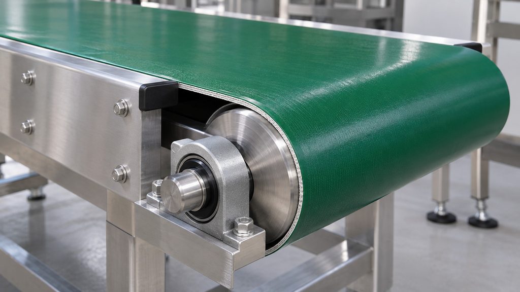
A conveyor belt runs to one side when the forces across its width or along its path are uneven. Pulley and roller geometry, off-center loading, buildup, take-up condition, and the belt’s construction or joint can all contribute. Record where and when the belt moves before deciding whether the conveyor needs correction or the belt specification needs review.
What Is Conveyor Belt Tracking?
Conveyor belt tracking describes the belt’s lateral position as it travels around the machine. A belt can run at the expected speed and still drift sideways. Drive slip is relative movement between the belt and drive pulley, so record loss of speed separately if both symptoms occur.
Use operating records or observations from an approved guarded position to identify the pattern. For physical inspection, cleaning, measurements or adjustments, follow the machine’s service procedure and energy-isolation requirements. In covered US workplaces, OSHA’s hazardous-energy control standard applies to relevant servicing activities. Any necessary operating test belongs to qualified personnel working under machine-specific safeguards.
What Causes Conveyor Belt Tracking Problems?
Geometry and support. A pulley out of square, a shifted roller mount or a distorted frame can change how the belt enters the next span. A worn bearing or seized roller can also make one part of the belt path behave differently. Compare the geometry with the machine datum and drawing, especially near recent service work.
Loading and contact. Packages delivered toward one edge, or pushed sideways by a transfer or diverter, can introduce lateral forces. Note where the load lands and whether the change coincides with product arrival. Buildup on one side of a pulley or return roller can alter its effective surface. The NIBA Conveyor Belt Tracking Guide emphasizes the importance of clean, properly aligned components. Check the return path as well as the carrying side.
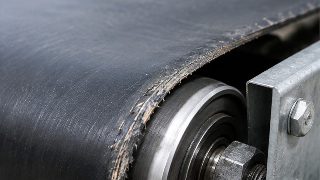
Take-up, belt and joint. A skewed take-up changes the geometry of the belt path. Longitudinal belt curvature (camber), uneven edge length or a misaligned splice can contribute to movement that repeats as the same belt section passes. Compare the entire loop and original specification. As Forbo’s Transilon product-structure guide explains, the reinforcement and underside construction also affect running behavior and support compatibility.
How Can You Assess Different Tracking Symptoms?
Record the first affected station, the edge involved, the travel direction and the load state. If the joint is visible from an approved observation point, note whether the movement repeats as it passes. A symptom narrows the investigation. The checks below are for qualified personnel working under the applicable service procedure.
| Observed symptom | Possible causes to investigate | Relevant evidence | Next technical check |
|---|---|---|---|
| Belt consistently moves toward one side | Pulley or roller skew, frame distortion, uneven buildup | Drift starts at the same station under several operating conditions | Compare mounting, pulley and frame geometry with the machine datum |
| Belt moves sideways once per circuit | Joint geometry, local belt damage, camber or an attachment irregularity | Movement follows the same belt section | Inspect the joint, edges and nearby guide section on the isolated belt |
| Drift comes and goes irregularly | Intermittent side feeding, changing buildup, roller or tracker fault | Event coincides with a load change or equipment cycle | Compare timestamps and inspect the affected support or tracking device |
| Belt centers empty but drifts loaded | Off-center feed, side force at a transfer, support movement under load | First movement follows product contact or heavier duty | Review feed position, diverter contact and support condition |
| Drift begins after replacement | Changed width, underside, joint or guide offset, or changed installation geometry | Old and new specifications differ, or a take-up or pulley was disturbed | Compare approved drawings and samples, then verify the installed arrangement |
| Drift changes on reversal | Direction-dependent steering, a different entry path or loading point | Drift starts at a different station or edge after direction changes | Check whether the tracking arrangement is approved for both directions |
| Edge rubs at one frame opening | Tight local clearance, displaced hardware, or upstream drift | Witness marks on the edge and a fixed machine surface | Locate where the belt first leaves its path and inspect the contact point |
| Underside guide shows wear on one flank | Groove offset, interference at a transition, or sustained lateral load | Guide wear concentrates on one side or near a particular station | Compare guide and groove positions, cross sections and clearance through the route |
Separate a fixed machine location from a feature that travels with the belt. Drift that starts at the same roller makes that station a useful place to inspect. Movement that follows the joint gives you a reason to inspect the splice and adjacent belt. Both observations can coexist. A tight frame opening may expose a small joint-related movement that would pass unnoticed elsewhere.
For a repeatable fault record, use the same machine-side reference in every observation. Note the belt travel direction, first point of lateral movement, load state, time or operating cycle, and any recent belt or equipment change. This helps the maintenance team compare patterns without treating an observed correlation as a confirmed diagnosis.
How Do Pulley Alignment and Crowned Pulleys Affect Tracking?
A geometry review should cover the frame, pulley axes, roller mounts and supports. A designed steering arrangement may be intentional, so compare the installation with its approved drawing. The relationship between components matters more than any single reference reading. LKBELT’s conveyor components and belt compatibility guide explains how these machine features affect belt specifications.
Crowned or cylindrical-conical pulleys can help center a suitable fabric belt. Their effect depends on pulley geometry, the unsupported span, belt construction and conveyor layout. Forbo’s machine-design recommendations discuss configurations where the centering effect is limited, including certain short, wide conveyors. A pulley whose shape or condition differs from the drawing warrants inspection before anyone changes the tracking design.
On a reversing conveyor, the belt approaches components from the opposite direction. A roller arrangement that steers acceptably in one direction may behave differently in the other. Describe each direction using a fixed machine reference, such as the operator side, so the two observations are comparable. Check the approved arrangement for both directions before changing hardware.
Can Belt Tension Fix Tracking Problems?
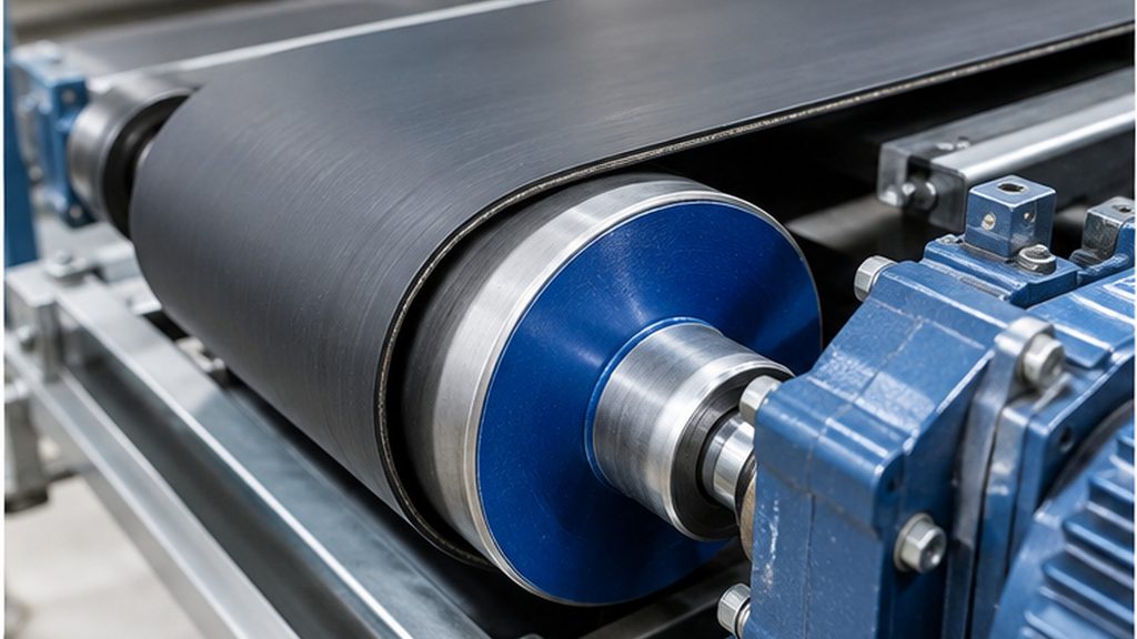
The take-up maintains the working tension required by the drive. Its position and alignment also affect how the belt approaches nearby pulleys. Check tension and geometry separately. A belt may have adequate traction and still mistrack because its pulley is skewed or its load is biased to one side.
Extra tension increases forces on the belt, joint, shafts and bearings. An apparent improvement after a tension change can leave the original cause unresolved. Use the equipment and belt specifications to check the installation. If the take-up is near a travel limit after replacement, record the available travel and verify the ordered length reference and installed route.
When Are Tracking Guides or Guiding Rollers Appropriate?
A guiding roller acts on the belt path. An underside guide interacts with grooves or clearances in the conveyor. Their suitability depends on where lateral forces occur, the belt construction and the travel direction. Where the machine already has an automatic tracker, have qualified personnel check its sensing and actuation against the service instructions.
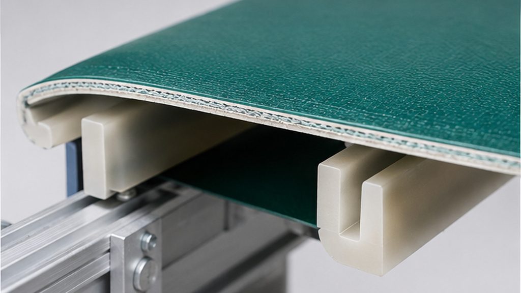
For an existing underside guide, record its cross section and position from a named belt edge. Compare those dimensions with the pulley and support grooves, including transitions where a guide could bind. Check bending requirements, the guide joint and the operating conditions. Continuous flank wear can indicate that the guide is carrying a lateral force or encountering interference. Correct significant machine misalignment through the equipment service process.
LKBELT’s published conveyor-component information includes K/KN6 (6 × 4 mm) and K/KN10 (10 × 6 mm) guide examples, expressed as bottom width × height for those documented profiles. These measurements identify a guide section, not its position on the finished belt. Specify the edge offset, matching groove, joint arrangement and pulley path as well. The conveyor belt accessories range provides related product context; a guide does not substitute for correcting substantial frame or pulley misalignment.
Why Does Tracking Change After Installing a New Belt?
Start with what changed. The finished width affects side clearance. A length difference can move the take-up to another part of its travel. A different underside can change contact with the support, and different reinforcement can change how the belt bends and responds to load. Compare the joint type, guide offset and full construction with the approved original.
Installation may also have disturbed a pulley, bearing mount, bed or take-up. Separate measured belt differences from machine changes in the service log. Compare the original drawing with actual finished-belt dimensions, recording the length reference, width and guide offsets consistently; LKBELT’s conveyor belt measurement guide explains how to prepare those specifications. If the belt matches the drawing but still drifts, the symptom pattern can help prioritize machine checks. If it appears out of specification, document the discrepancy using measurements from the isolated assembly.
Assess fraying, cuts or exposed reinforcement separately. Correcting the lateral path does not automatically resolve the damage already present; LKBELT’s conveyor belt repair-versus-replacement guide explains the separate decision.
Two Practical Troubleshooting Scenarios
A Packaging Conveyor Drifts Only with Product on It
Imagine that a light packaging belt runs near the center when empty but moves toward the operator side after cartons enter from a transfer. Record where the first lateral movement occurs, where the cartons land and whether the drift changes with carton size or feed pattern.
The maintenance team can use those observations to prioritize the transfer, diverter and nearby support. If the same station also starts to drift when empty, broaden the review to roller condition, buildup and alignment. Purchasing can hold the replacement decision until maintenance knows whether the existing belt is damaged or the duty requires a different construction.
A Replacement Fabric Belt Rubs at the Return
Imagine a PVC or PU fabric belt begins rubbing shortly after installation. The top surface looks similar to the old belt. At one return station, the underside guide has a fresh mark on one flank.
Compare the old and new finished widths, the guide offsets from the same edge, and the guide section and joint. Check the groove at the marked return station and the pulleys leading into it. If the dimensions match, inspect the installed support and take-up geometry. If the guide offset differs, send both drawings and the location of the rub for a specification review. Either route produces a clearer request than ordering another belt by top surface and width alone.
What Information Should Buyers Provide When Replacing a Mistracking Belt?
Put the original specification and operating observations in the same inquiry. LKBELT’s PVC sawtooth conveyor belt guidance asks for tracking marks, surface wear, underside and joint photographs, as well as dimensions and guide information where relevant. The purpose is not to assume this pattern suits every system, but to show the level of detail a useful replacement request needs.
- Machine model, installed position, original part number and drawing revision.
- Original and measured finished width, length with its measurement reference, thickness, underside and reinforcement where known.
- First drift location, affected edge, empty or loaded condition, travel direction and when the issue began.
- Pulley and support layout, take-up position, and any components disturbed during installation.
- Guide cross section and offset, matching groove drawing, joint type and installation access.
- Labelled photos of both edges, top and underside, joint, guide and contact marks.
- Product conveyed, load, speed, cleaning conditions, changes since the original order and quantity.
Label each dimension as taken from the approved drawing or measured on the used belt. Include any remaining unknowns so the quotation can address them.
Frequently Asked Questions
Why Does My Conveyor Belt Keep Moving to One Side?
Start with the first station where it moves. Check whether the pattern is tied to that location, to loading or to the same section of belt every circuit. Those observations help prioritize the inspection.
Can Too Much Tension Cause Tracking Problems?
It can aggravate problems through increased loads or deflection. Verify the specified tension and the take-up alignment independently.
Do Crowned Pulleys Always Center a Belt?
Their effect depends on the belt and conveyor design. Confirm the specified pulley shape and check the rest of the belt path.
Will a V-Guide Prevent Conveyor Belt Mistracking?
A correctly specified guide can help manage lateral movement on a compatible conveyor. It still needs suitable grooves and clearance, and the machine must be aligned.
Can Tracking Problems Cause Edge Damage?
Repeated contact can fray or cut a belt edge. Record the first point of drift as well as the contact mark, then assess the damage separately.
Decide What Needs Correcting Before Ordering
Use the symptom record to identify the next equipment check, belt inspection or specification comparison. If a replacement is warranted, send LKBELT the drawing, belt details and observed operating conditions for a focused quotation.