Double-sided PU timing belt
The product photograph shows a red profiled surface on one side and a light-coloured toothed surface on the other. For a replacement, send photographs of both sides and a cross-section drawing so the working surface, tooth profile and finished thickness can be matched to your assembly.
| Item | Product details |
|---|---|
| Belt type | Double-sided PU timing belt |
| Surface shown | Red profiled side and light-coloured tooth side |
| Tooth profile | Match to your pulley drawing or belt sample |
| Finished size | Specify width, length and overall thickness |
| Surface geometry | Include profile shape, spacing and alignment |
Send the full belt marking, cross-section and operating conditions with your inquiry.
Match both working surfaces
Show the tooth-side dimensions and the opposite surface separately on the drawing. Include any grooves, raised sections or shaped contact areas, together with their position along the belt. For a replacement, also provide the pulley arrangement and the machine part number.
| Detail | Information to provide |
|---|---|
| Belt dimensions | Width, finished length or tooth count, tooth height and overall thickness |
| Surface layout | Cross-section, profile spacing, grooves and the alignment of features on both sides |
| Construction | PU belt specification, required material for the opposite surface, tensile-cord material and joint arrangement |
| Machine conditions | Pulley drawing, speed, load, working temperature and contact with oils or cleaning agents |
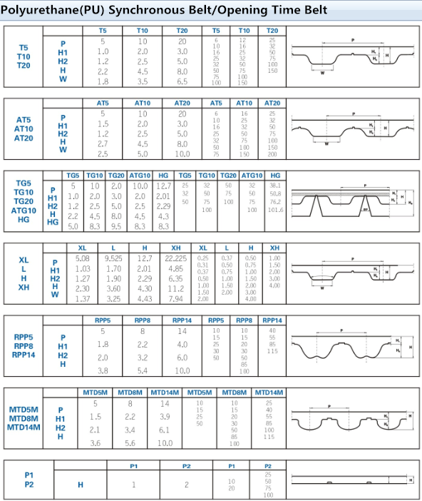
Timing belt series reference
The table below covers 22 timing-belt profiles. These series dimensions do not define the complete cross-section of the double-sided belt shown. Specify the geometry of each side and the overall finished thickness on your drawing; use the profile designation and pitch to discuss the pulley match.
| Profile | Pitch (mm) | Tooth thickness (mm) | Belt thickness including teeth (mm) |
|---|---|---|---|
| T2.5 | 2.5 | 0.7 | 1.6 |
| T5 | 5 | 1.2 | 2.2 |
| T10 | 10 | 2.5 | 4.5 |
| T20 | 20 | 5 | 8 |
| AT5 | 5 | 1.2 | 2.7 |
| AT10 | 10 | 2.5 | 4.5 |
| AT20 | 20 | 5 | 8 |
| H | 12.7 | 2.29 | 4.29 |
| XH | 22.225 | 6.35 | 11.2 |
| L | 9.525 | 1.91 | 3.61 |
| XL | 5.08 | 1.27 | 2.3 |
| 3M | 3 | 1.21 | 2.4 |
| 5M | 5 | 2.1 | 3.7 |
| 8M | 8 | 3.38 | 5.6 |
| 14M | 14 | 6.1 | 10 |
| S3M | 3 | 1.14 | 2.9 |
| S5M | 5 | 1.85 | 3.35 |
| S8M | 8 | 3.05 | 5.3 |
| S14M | 14 | 5.3 | 10.2 |
| RPP5M | 5 | 2.05 | 3.8 |
| RPP8M | 8 | 3.2 | 5.4 |
| RPP14M | 14 | 5.85 | 9.7 |
Timing belt profile illustration
This illustration covers several profile families. Match the applicable tooth geometry to your pulley; specify the opposite surface and finished thickness separately.