
When a packaging drive loses registration or a linear axis starts shedding belt material, the damaged belt is often the first part maintenance removes. Before ordering another one, record what changed and where the damage appeared. A worn pulley or an altered motion cycle can damage the replacement in the same way.
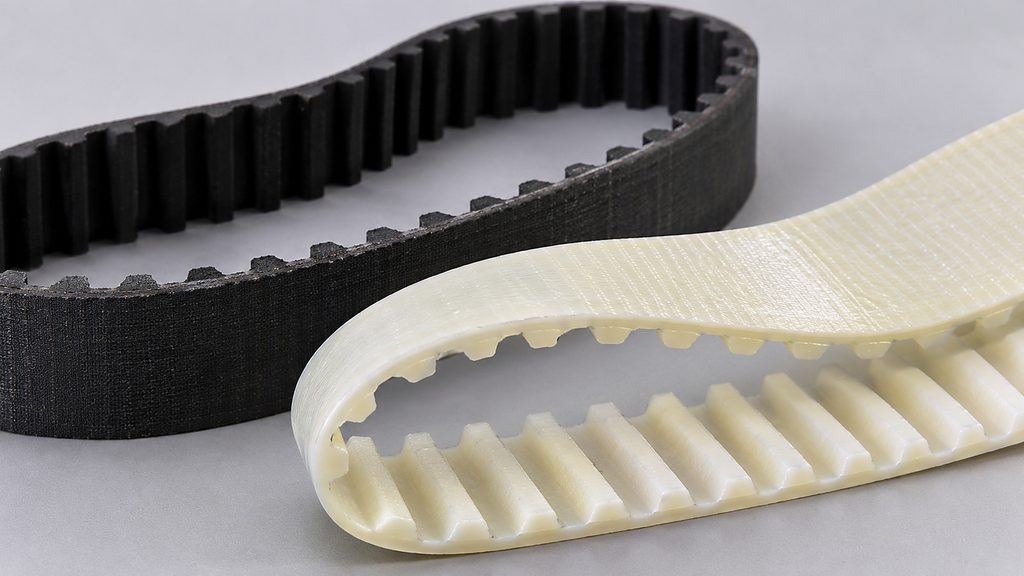
Industrial timing belt failure can result from poor tooth engagement, incorrect installed tension, shock loads, misalignment, repeated bending, or exposure outside the belt’s specification. Tooth damage, cracks and unusual noise help direct the investigation. Compare the belt, pulleys and operating history before deciding what needs correction and what belongs on the replacement order.
What Are the Common Signs of Industrial Timing Belt Failure?
Separate physical damage from changes in machine behavior. Missing teeth, polished flanks, backing cracks, frayed edges and exposed reinforcement are findings on the belt. A sudden phase change, recurring position error, unusual noise, vibration or heat is a finding on the drive. Record the time and location of both. A drive can lose registration while its belt teeth still appear intact.
Use existing production logs and observations from approved guarded positions. Physical inspection, measurement and corrective work belong under the machine’s service and energy-control procedures. Qualified personnel should conduct any necessary energized test under applicable safeguards. In covered US workplaces, OSHA’s hazardous-energy control standard applies to servicing and maintenance where unexpected energization, startup or stored energy can cause injury.
What Causes Industrial Timing Belt Failure?
Start with the change history. Damage that begins after a pulley or belt change warrants an early compatibility check. A problem that first appears after a faster acceleration ramp warrants a review of peak load and engagement. If the drive has run the same duty for months, look for wear, loose mounting, debris or a change in the environment. Dates and machine records help rank these possibilities.
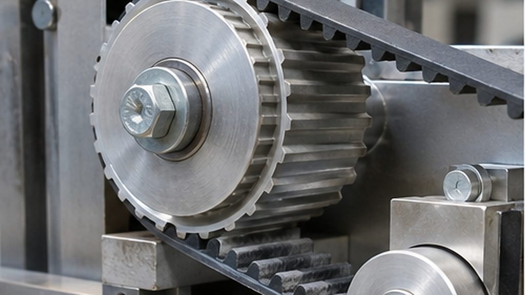
Review the complete belt path. Pulley tooth geometry, alignment, runout, flange condition, idler placement and the rigidity of the mounts can influence how forces are distributed. Check the pulley and idler diameters against the documentation for the installed belt and any added backing. A backside idler can introduce reverse bending even when the main pulleys are unchanged.
Storage and installation deserve their own record. A spare that was sharply folded, or a belt that was forced over a flange, may have been damaged before it ran. Keep packaging and installation records if the failure appeared early. The Gates Industrial Preventive Maintenance Manual, pages 53–54 identifies geometry, handling, contamination and operating conditions among the issues worth investigating.
Industrial Timing Belt Failure Diagnosis Matrix
Preserve the removed belt and label its installation orientation, tooth side and affected edge. Record where damage sits relative to a joint or clamp. If an event repeated during normal operation, note whether it followed the same belt section, the same shaft position or the same point in the machine cycle.
| Observed symptom | Possible causes to investigate | Evidence to record | Next technical check |
|---|---|---|---|
| Tooth flanks polish or wear unevenly | Poor groove fit, rough or worn pulley, abrasive debris, uneven engagement | Which flank and how much of the width is affected, groove condition, debris location | Compare the belt and pulley drawings and inspect the mating surfaces |
| One tooth or a group of teeth shears | Shock load, inadequate engagement, mismatch, pulley damage | Extent of tooth loss, debris, jam history, recent changes | Review peak duty, pulley fit and engagement geometry |
| Registration shifts with teeth still present | Tooth skipping, hub movement, encoder or control issue | Abrupt or gradual shift, alarm history, shaft references and event timing | Compare commanded and actual motion and check the mechanical connection under the service procedure |
| One edge frays or cords become visible | Flange contact, drive misalignment, side interference or clamp damage | Affected edge, matching witness marks, distance from clamp or joint | Inspect mounting, flange clearance and contact points |
| Backing cracks, separates or changes texture | Repeated bending, storage damage or incompatible exposure | Crack distribution, idler route, cleaning agents and temperature history | Review the full belt construction and duty against supplier documentation |
| Belt breaks across its width | Sudden load, repeated cord damage, installation damage or foreign-object entry | Both break ends, earlier wear, load records and pulley path | Request technical review of the belt and drive before approving the replacement |
| Joined loop opens at the splice | Duty exceeds the approved joined construction, local damage or joint issue | Joint location, adjacent tooth condition, supplied construction and duty history | Confirm the permitted application for that finished joint |
| Noise, vibration or heat increases | Contact, pulley or bearing condition, incorrect tension or loose support | Location and conditions from approved observations, existing alarms and service records | Check the affected component and compare with the drive specification |
Why Do Timing Belt Teeth Wear, Shear or Jump?
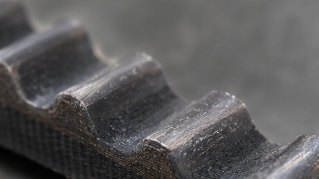
Tooth wear is gradual material loss. Shear is physical damage where part or all of a tooth separates. Tooth skipping (ratcheting) occurs when teeth lose engagement and re-engage out of position. It can happen while the teeth remain visibly intact; physical tooth damage may develop separately. Record changes in machine registration and belt condition as two distinct observations.
Equal nominal pitch leaves other compatibility questions open. Compare the tooth profile and pulley groove design, particularly after an idler or pulley change. For an inquiry involving LKBELT’s TK10 (13×8) PU timing belt, retain the full designation and provide a pulley drawing or existing belt sample. TK10 should not be treated as a conventional T10 substitute simply because the names look similar. For an introduction to tooth pitch and belt selection, see the industrial timing belt guide.
What Do Cracks, Exposed Cords and Edge Wear Indicate?
Map backing cracks before cleaning or discarding the belt. Cracks distributed along a span and damage concentrated at one bend or clamp provide different starting points. Compare the route and bending history with the timing of a washdown, temperature change or prolonged storage. The visible crack pattern alone leaves the mechanism uncertain.
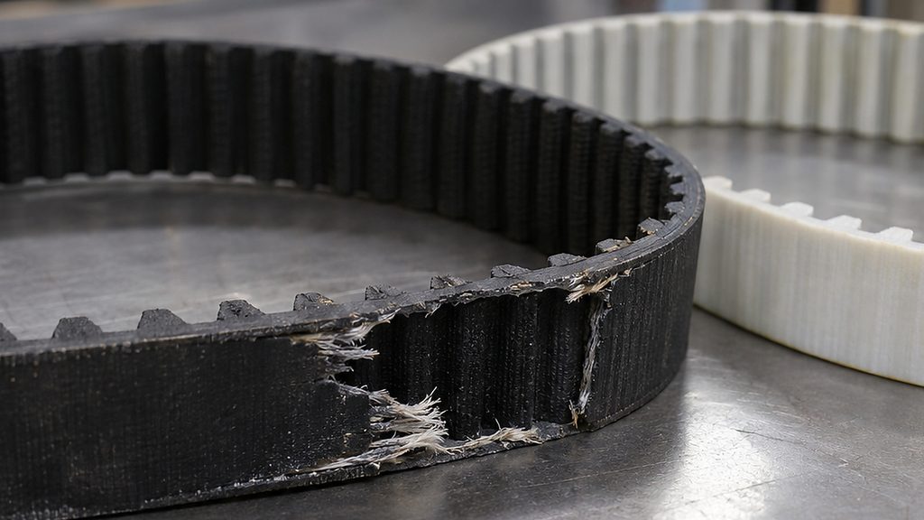
An exposed cord shows that material around the reinforcement has been lost or displaced. The cord may appear intact at that spot, but the belt still requires qualified assessment rather than an assumption that it can remain in service. Fatigue damage accumulates under repeated loading or flexing and may not be visible without closer examination. Retain both ends of a rupture and any fragments for review.
If one edge is polished or frayed, look for corresponding marks on a flange, guard or nearby structure. Record the edge in machine coordinates. An edge may have been damaged by contact before it started wandering, or the contact may follow an alignment problem elsewhere in the drive.
Can Incorrect Tension Cause Timing Belt Failure?
Insufficient pretension can make engagement less reliable during a load peak. Excessive pretension increases tensile loading and the forces carried by pulleys, shafts and bearings. Both can contribute to premature damage. The correct setting and measurement method depend on the particular drive.
Treat installed tension, operating load and engagement geometry as separate checks. A reading taken after a belt has stretched, shed teeth or moved in a clamp may differ from its condition before the event. Use commissioning records where available, identify the condition of any new reading and have qualified personnel assess it against the equipment procedure. Increasing tension leaves a worn groove or inadequate engagement geometry unresolved.
Do PU, Rubber and Belt Form Affect Failure Analysis?
Identify the belt body, tensile members and any facing or backing separately. PU and rubber are broad material categories. Compare the actual compound and construction with the agents used for cleaning, the temperature history and the contact surfaces. Backing damage may concern an added layer, while the underlying body and reinforcement require their own assessment.
On an open-ended linear drive, inspect the clamp area and the adjacent unsupported span. Confirm the required engagement at the clamps, the end arrangement and the operating stroke. For a loop, establish whether it was manufactured truly endless or joined. If damage starts at a weld, review the joint and approved duty for that specific belt. A failed joint provides no general strength ratio for other spliced belts.
Cord material and construction belong on the replacement record, especially when repeated bending or reversal is under review. LKBELT’s T10 Kevlar-cord PU timing belt illustrates why reinforcement should be recorded alongside the tooth system. The applicable limits still depend on the finished belt and its route.
When Should a Timing Belt Be Replaced?
A broken belt, missing teeth, exposed reinforcement or an opening joint calls for prompt assessment under the site’s procedures. Preserve the evidence and let qualified personnel determine the equipment status. Use the manufacturer’s criteria to assess the belt’s condition and the proposed replacement.
If the belt is damaged and the pulley is worn, record both decisions. Replace the damaged belt as required and resolve the pulley condition before commissioning. Where failures recur or the application has changed, have engineering review the duty and finished construction before repeating the old order. Retain the previous specification as a comparison.
Two Practical Industrial Failure Scenarios
A packaging drive loses registration
Suppose a machine produces a sudden registration offset after a jam. Maintenance finds the belt teeth still present. Save the cycle and alarm records, document the offset and preserve any existing shaft-to-hub reference marks. Under isolation, inspect tooth flanks and pulley grooves and check for evidence of hub movement. The event could involve a skip or a shifted connection. If the error returns progressively with speed, review the motion records and supporting hardware before concluding that a different belt will restore registration.
A reversing linear axis shows damage near a clamp
Suppose a carriage develops early edge wear and exposed reinforcement near one end. Record which end and edge are involved, the affected stroke position and whether acceleration or reversal changed recently. Compare the clamp and pulley route with the approved drawing, including the smallest bend and any reverse bend. If the damage follows a particular clearance or clamp contact, correct that condition through the equipment procedure. If the motion duty changed, include the revised cycle and the original reinforcement in the engineering review.
What Should Buyers Send When Ordering a Replacement Timing Belt?
Separate the approved specification, observations from the failed assembly and proposed changes. If the original information is incomplete, send the drawing and clearly labelled photos. For LKBELT’s RPP5M-PAZ PU timing belt, the product inquiry requests both tooth-side and outer-surface views along with the marking or pulley drawing and finished dimensions. These details help identify a required facing or backing when the worn sample alone is ambiguous.
- Machine model, installed position, full belt marking and drawing revision.
- Tooth profile and pitch, finished width and pitch length or tooth count. For an open-ended belt, specify cutting length and clamp arrangement.
- Body material, tensile reinforcement, tooth facing, backing and required supply form or joint.
- Pulley identification, tooth geometry, tooth counts, face width, flange condition and idler arrangement.
- Damage locations and photos of the tooth face, backing, both edges and any joint or clamp area.
- Load, speed, starts, acceleration, reversals, temperature, contamination, cleaning conditions and recent duty changes.
- Quantity, required tolerances and fields that still need confirmation.
Frequently Asked Questions
Why do industrial timing belt teeth break?
Shock loading, unsuitable engagement or poor pulley fit can damage teeth. The condition of the remaining teeth and grooves and the timing of the event help narrow the cause.
Can a timing belt jump teeth without breaking?
Yes. A tooth can leave its groove and re-engage out of position. A phase change with intact teeth warrants a drive investigation.
Does excessive tension damage timing belts?
It can increase loads on the belt and drive components. Compare installed tension with the specified method and setting for the assembly.
What causes timing belt edge wear?
Check for flange or structure contact, poor alignment and interference at clamps or adjacent hardware. Photograph matching marks and identify which edge is affected.
Can I reorder the same model?
Confirm that the original belt still matches the pulley system and current duty. Address any equipment fault or installation discrepancy before commissioning the replacement.
Specify the Replacement Against the Complete Drive
Keep the damage record with the order specification so maintenance and purchasing can review the same belt, pulley and duty information. Review LKBELT’s industrial timing belt range once the required construction is established, then send the confirmed specifications for a replacement quotation.